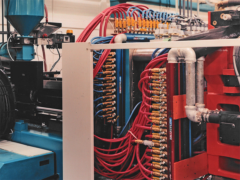
Molding is a complex business. From a technical perspective there is much to know. Molders must be versed in materials science and the workings of a molding press. They must know about hydraulics and electrical controls. And they should even be at least “shade tree” tooling experts, familiar with steels, heat treating, runners and gates, and mold cooling.
Of these tooling facets, it could be argued that mold cooling is one of the most important. A slight difference in cooling conditions can add or subtract seconds from the molding cycle, making the difference between a profitable molding job and a loser. Critical dimensions, surface finish, and part warpage are all affected by cooling conditions. It is ironic, then, that mold cooling is the neglected stepchild in many molding shops. We have all sorts of “gee-whiz” technology for monitoring and controlling nearly everything but mold cooling.
Like most things, there is more to know about the finer points of mold cooling and heat transfer than most of us care to learn. In fact, you could probably write a good PhD dissertation on mold cooling if you wanted to. But we’re not going to consider those complexities here. Although most molders have an idea of what mold temperature they need, they often have no idea how many gallons per minute of water they need through a cooling circuit or what size hose and fittings to use. These are some of the simple, common sense things to know on this subject; useful, well-conceived products can give you better information and control over mold temperatures. This article aims to help you gain a better understanding of mold cooling and to be helpful in your molding efforts.
Turbulent Flow
Let’s start with some engineering basics. Most of you have heard something about turbulent flow and that it is good for cooling. But just what is turbulent flow? How does it help? What flow rates are needed to achieve turbulent flow?
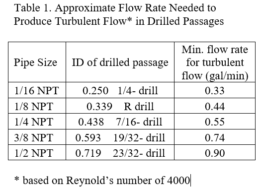
Turbulent flow begins when the velocity of fluid in a channel increases to a critical level. Above this critical velocity, vigorous internal mixing of the fluid occurs as it flows. This improves heat transfer by mixing warmer fluid near the wall of the cooling passage with the relatively cooler interior fluid. the precise velocity for turbulent flow depends on several variables, including the cooling passage geometry, fluid viscosity, and roughness of the pipe walls. The formula for a ratio known as Reynold’s number includes these variables. A Reynold’s number greater than 3000 denotes turbulent flow.
Table 1 shows some values for normal mold cooling situations with water as the fluid.
Having said this, I can tell you that in some cases turbulent flow doesn’t matter too much, and in other cases it matters a lot. In one example, the cycle time for a coffee mug with a 0.200-inch thick wall was very poor. The molder wanted to improve the cooling in the mold cores with the goal of achieving a substantial cycle improvement and spent a significant sum making cooling “improvements”. When the mold was sampled, the molder was surprised to learn that the cycle was about the same as before. What was going on there?
The best cooling system in the world won’t take away heat any faster than the molded part will give it up. Most unfilled resins transfer heat at a rate 1/10 to 1/25 that of steel. The outer walls of a thick part insulate the mold from the heat trapped in the center of the part. The message here is that for very thick part, the cooling system will have relatively little effect on cycle time. the other hand, let’s say you are running a very thin polyethylene lid. This part can give up its internal heat quickly because of its thin walls and typically runs on a fast cycle.
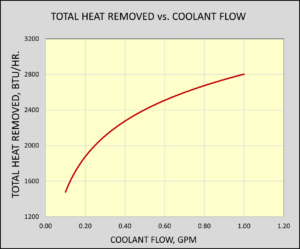
These factors combine to greatly increase the demands on the cooling system, so good cooling performance requires well-placed passages in the mold as well as greater flow rates to carry away the heat. Thus, it is generally true that if the molded parts will give up their heat, it is worthwhile to use higher cooling flow rates. And it is true that the faster the flow rate, the more total heat you remove — even though the change in the temperature of the water flowing through the mold is very slight. Intuition may suggest that the water would pick up more heat at a slower flow rate, but it won’t. Although the temperature of the water increases more at a slower flow rate, total heat removed does not. Data gathered in our laboratory (Figure 1) illustrate this point.
Figure 1: Amount of heat removed by varying water flow rates in Simulated Mold with 1200-W electrical resistance heat input.
Temperature Control
In some cases you may want slower flow, and special systems are available for these situations. For example, you may have a mold that runs only if the cores are a few degrees warmer than the cavities, or vice versa. To warm up the desired zone, you merely throttle the cooling flow. A fancy name for this is heat recovery temperature control. In other words, you recover heat from the molding process to elevate the mold temperature. You may have noticed that it is very difficult to settle a mold into a steady-state condition. You’re always chasing the temperature up and down. If you are ambitious, you might hook up a mold heater to solve the problem. But there is an easier way. Heat recovery temperature control systems are available that electronically monitor cooling circuit temperature and automatically throttle flow to maintain a set temperature. The temperature sensor is normally placed in the water return from the mold but can even be placed in the mold steel. This system will not replace a mold heater in situations that require adding heat from outside the mold — when the mold must be hot before you can start molding, for example. But it can make life easier when different zones require slightly different temperatures or when you want to run a mold warmer than tower or chiller water allows at full flow. These systems allow you to throttle the flow with precise temperature control. With their modest initial cost and operating energy savings, heat recovery systems can be an attractive alternative to traditional mold heating systems. The accompanying box illustrates an example of this.
Flow Rates
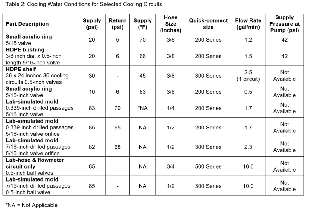
With the preceding basics in mind, let’s look at some cooling conditions in actual molding situations and some data taken from lab experiments. Once you decide you need a certain flow rate, you need to know what it takes to get there. Table 2 shows cooling data taken from selected operating molds and from our lab. Higher flow rates can be achieved by increasing pressure or reducing flow resistance.
If you are installing a new plant circulating system, it’s a good idea to pay careful attention to the pressure issue. This means using a big enough pump and large enough distribution lines throughout the plant. But when you are stuck with the water delivery system you already have, you must work on reducing resistance. Here are some suggestions.
Design mold cooling passages as large as practical to reduce resistance to flow. Next, look at the size of pipe or quick-connect fittings going to the mold. Note in Table 2 the change to 2.3 gal/min from 1.7 gal/min brought about just by changing from 200 series to 300 series quick-connect fittings and changing to a slightly larger drilled passage. The same effect generally follows increasing hose sizes. For example, our lab has an available water pressure of 85 psi, but it is impossible for more than about 2.5 gal/min to flow through 0.25-inch hose. In many plant situations, water pressure is much lower than 85 psi.
Water manifolds can also make a big difference. It does no good at all to have 12 0.5-inch NPT(National Pipe Taper) fittings coming off a manifold with only a 0.75-inch NPT inlet to supply all those fittings. A well-designed manifold should have a supply area roughly equal to the discharge area, or as large as practical. For example, 16 0.5-inch NPT fittings require about a 2-inch NPT supply for best performance. Also, the main supply and return fittings and hoses to the manifolds should not be smaller than the manifold inlet. Attention to these details can improve the pressure available at the mold.
If you are interested enough in all of this that you would like to learn more about your cooling conditions, you need to know what equipment is available to monitor and control flow rates, pressure, and temperature in your mold cooling circuits. A number of companies offer products to distribute cooling water and to monitor or control mold cooling variables. They, and others, can help meet your equipment needs and offer technical assistance if you have questions.